Model Definition (.mdl)
Models are stored in the .mdl format. The format consists of geometric information for different levels of detail (LODs) and metadata. For each LOD, there is a separate hierarchy of nodes with their meshes, animations, events, and materials. In general, .mdl files contain a data()-function that returns a struct similar to the one below:
function data()
return {
  boundingInfo = { ... }, -- optional bounding box used e.g. for render borders
  collider = { ... },     -- optional collider for collision calculation
  lods = { ... },         -- geometric information for 3D data and textures
  metadata = { ... },     -- metadata depending on model type
  version = 2,            -- new Transport Fever 3 format
}
end
Bounding Box
The bounding box is a cuboid that encloses the outermost elements of the model so that all parts of the model lie within the box. It is used, for example, to decide whether an object is within the visible range of the camera and needs to be rendered or not. It should also include the volume of the light emitters to ensure they do not plop in at the screen edge.
  boundingInfo = {
	bbMax = { <+x>, <+y>, <+z>, },
	bbMin = { <-x>, <-y>, <-z>, },
  },
The values are the distances from model origin in positive and negative direction on all three axis.
Collider
The collider struct is used whenever the potential collision between models is considered. It's possible to use the mesh data for collision calculation as well as define the collision boundaries by script.
Collider from Mesh
When the mesh data should be used for collision calculation, the type "MESH" is needed:
collider = { params = { }, transf = { 1, 0, 0, 0, 0, 1, 0, 0, 0, 0, 1, 0, 0, 0, 0, 1, }, type = "MESH", },
Collider from Script
When the boundaries should be set by script, the type "BOX", "CYLINDER" or "POINT_CLOUD" is needed:
collider = { params = { halfExtents = { 1.5, 1.5, 1.5, }, }, transf = { 1, 0, 0, 0, 0, 1, 0, 0, 0, 0, 1, 0, 0, 0, 0, 1, }, type = "BOX", },
The size of the volume is specified by 2 times the halfExtents properties for the "BOX" and "CYLINDER" type. It can be offset relative to the model origin with the transf property. The "POINT_CLOUD" uses a list of points that is provided in the points property. Each point has three values for the position on all three axis relative to the construction origin and the transf property is ignored.
Level of Detail
To realize both detailed models and decent game performance at the same time, mdls provide the full detail models as well as simplified ones, the so called Levels of detail (LOD). They are used when the distance between model and camera increases, thus saving computing power during rendering. At least one LOD is needed, but it is recommended to include more if the model has a large number of tris.
  lods = {
	{
	  node = { ... }
	  static = false,
	  visibleFrom = 0,
	  visibleTo = 200,
          textureLodBase = false,
	},
	...
  },
The node element is the top level of the mesh hierarchy in this LOD.
The range of visibility is limited by visibleFrom and visibleTo.
The textureLodBase is a boolean attribute that needs to be set to true if materials with textures are used from a specific level of detail onwards, e.g. buildings that use baked textures for LOD1 and following should have LOD1 with textureLodBase set to true.
Performance Optimization
To reduce the performance impact of a model, there are several approaches that should always be followed:
- Keep the tris count to a useful minimum. Vehicles should not have unreasonable amounts of tris, 100.000 tris should suffice in most cases. Try to divide the tris by 4 for every LOD. The last LOD should have only a few 100 tris, if possible.
- Keep the number of different materials per LOD to a minimum. Where there is no reason to use seperate material, don't do it.
- Keep the number of meshes to a minimum. No need to have every seat of the vehicle as a seperate seat. Seperate windows in LOD 0 are ok to ensure proper sorting of transparent materials, but in LOD 1/2/… they can be merged.
- Keep the number of sorted materials to a minimum. The benefits of sorted materials are only visible when the transparent surfaces are large, hence there is no need to have a sorted material for LOD 1 and beyond.
Hierarchy Nodes
The hierarchy is defined by nesting of nodes. The root node is the top level parent node. A node can have the following attributes:
{ children = { ... }, transf = { 1, 0, 0, 0, 0, 1, 0, 0, 0, 0, 1, 0, 0, 0, 0, 1, }, animations = { ... } mesh = "path/to/mesh.msh" materials = { ... } name = "mesh_01" }
childrenis an optional list that may contain more nodes recursively.transfis a 16 number transformation matrix to specify the position, scale and rotation of the node relative to its parent.animationsis an optional list of one or more animations assigned to events, see below.meshis an optional reference to a mesh file, it is transformed according to thetransf.materialsis a list of material file references. The number of references has to match the number of submeshes of the mesh.nameis a string that is used to reference this node in the metadata. It has to be unique per LOD and the names of the corresponding nodes in the other LODs should be identical.
For skinned meshes (e.g. characters, vehicle bellows and bridges/tunnels), the attributes differ slightly:
{ children = { { name = "bone_1", transf = { 1, 0, 0, 0, 0, 1, 0, 0, 0, 0, 1, 0, 5, 0, 0, 1, }, }, ... }, transf = { 1, 0, 0, 0, 0, 1, 0, 0, 0, 0, 1, 0, 0, 0, 0, 1, }, animations = { ... } skin = "path/to/mesh.msh" skinMaterials = { ... } name = "mesh_01" }
Animations
The animations struct contains a list of animations with eventnames as keys:
animations = { eventname = { params = { id = "path/to/animation.ani", -- relative to res/models/animation/ }, type = "FILE_REF", }, ... },
The eventname key is referenced by the transformators.
Further information on animation files can be found in the animation section.
It is possible to include the animation date directly in the .mdl as well, but the file reference method is recommended to keep the model file compact:
animations = { eventname = { forward = true, -- or false for inverse keyframe playback params = { keyframes = { { rot = { 0, 0, 0, }, -- rotation around all three axis time = 0, -- milliseconds since begin of animation transl = { 0, 0, 0, }, -- position offset for all three axis }, ... { rot = { 0, 0, 0, }, time = 1200, transl = { 0.75, 0.055, 0, }, }, }, origin = { 0, 0, 0, }, -- offset of animation origin from node origin }, type = "KEYFRAME", }, eventname2 = { forward = true, -- or false for inverse keyframe playback params = { keyframes = { { time = 0, -- milliseconds since begin of animation transf = { 1, 0, 0, 0, 0, 1, 0, 0, 0, 0, 1, 0, 0, 0, 0, 1, }, }, ... { time = 1200, transf = { 1, 0, 0, 0, 0, 1, 0, 0, 0, 0, 1, 0, 0, 0, 0, 1, }, }, }, }, type = "KEYFRAME_MATRIX", }, },
Meshes and Materials
Nodes can contain a mesh. Meshes consist of two files, meshname.msh with index information and meshname.msh.blob with 3D model data (binary). See the documentation of msh files for further information on meshes.
For each submesh provided by the referenced .msh file, a material has to be referenced.
materials = { "path/to/material.mtl", "path/to/secondMaterial.mtl", ... }
Further details about material files and types can be found in the material documentation.
Metadata
There is large set of metadata keys to describe all the different types of models in the game. Some of the keys can be used for almost every type of model. These are described below. For specific model types, the keys are described in the relevant sections of the wiki:
The following metadata keys can be applied to any or the majority of model types. Depending on the resource type, they might be mandatory, but can often be left empty to default to zero.
descriptionavailabilitycostmaintenanceextentcameraConfigloadIndicatorlabelListlightSourceListparticleSystemtransformatorConfig
Description
The description provides the name and a descriptive text for the model. It is used for vehicle informations in buy menu and status windows. Static models that are not part of a construction use it for the label in the menu. In constructions, these information are not used.
    description = {
      name = _("Name of Model"),
      description = _("Description displayed for example in the depot menu")
    },
Availability
The availability defines the timespan in which the model is available. yearFrom and/or yearTo can be left out or set to zero to define an indefinite start respectively end year.
    availability = {
      yearFrom = 1925,
      yearTo = 1985
    },
Cost
To activate automatic price calculation, set the price to -1. When price is left out, it defaults to 0. The value of priceScale can be used to adjust the calculated price. This is a hook up point for balancing mods too.
    cost = {
      price = 10000,
      priceScale = 1
    },
Maintenance
The maintenance metadata describes both the common running costs as well as the behavior of the vehicle in terms of wear down.
    maintenance = {
      runningCosts = -1,
      runningCostScale = 1,
      lifespan = 40 * 365 * 4,
      maintenanceScale = 1.0,
    },
To activate automatic maintenance calculation, set the runningCost to -1. When runningCost or lifespan is left out, it defaults to 0. The value of runningCostScale can be used to adjust the automatically calculated price. This is a hook up point for balancing mods too.
The lifespan value is the equivalent in quarter days with normal calendar speed. A full year equals 365 * 4 units.
The maintenanceScale describes the wear down intensity. With value 1.0, it takes 1/10 of the vehicles lifetime to reach 0 % maintenance level.
Extent
The extent describes the dimensions of the model for simulation purposes, e.g. the length for the simulation of vehicles, so the couplers attach properly.
    extent = {
      bbMax = { 6.20, 1.64, 4.53, },
      bbMin = { -6.43, -1.64, -0.03, },
    },
It's content is specified like the bounding box.
CameraConfig
By default vehicles, animals and people have an onboard camera that is relative to the node with the first crew seat or if no crew member is available, it is relative to the position and rotation of node 0. The cameraConfig allows for setting multiple custom camera positions, which can be cycled when the onboard camera is active.
    cameraConfig = {
      positions = {
        {
          group = "RootNode",
          transf = transf.rotYCntTransl(math.rad(25), vec3.new(0, 0, 0), vec3.new(-15, 0, 9)),
          fov = 90
        }
      }
    }
For every camera position, there is a struct in the positions list with several parameters:
groupis the name of the node that should be used as origin for the positioning of the camera.transfis the transformation matrix that is used for the positioning and rotation relative to the origin.fovis the field of view. Larger values result in wide angle views, narrow views can be done with smallerfovvalues.
LoadIndicator
There are three different ways to display cargo models in vehicles and static models, all configured in the loadIndicator property:
...
loadIndicator = {
  configs = {
    indicator_0 = {
      ...
    },
  },
},
...
The loadIndicator contains a configs map and an optional list of slots (see below). Each entry of the configs map needs to have an individual name that can be referenced elsewhere in the model, e.g indocator_0. It then contains one of the following types:
cargoBaydefines a volume within models are shown.cargoSlotsdefines specific positions at which models are shown.cargoLanesdefines lanes along which models are shown in a row.
CargoBay

discrete cargo bay
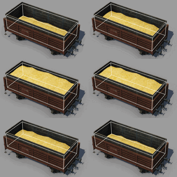
level cargo bay
A cargoBay is a box that is filled with cargo models depending on the amount of cargo that is loaded into the compartment:
...
loadIndicator = {
  configs = {
    bay_0 = {
      cargoBay = {
        bbMax = { 3, 1.348000049591064453125, 3.2000000476837158203125, },
        bbMin = { -3, -1.348000049591064453125, 1.192100048065185546875, },
        cargoFormats = { "SMALL", },
        childId = "body",
        gridSize = { 3, 2, },
        sizePolicy = "STRETCH",
        type = "DISCRETE",
      },
    },
  },
},
...
The cargoBay-struct has several properties:
bbMaxandbbMinare the parameter for the cargo bay bounding box that encloses the space of the model in which the cargo should be displayed. The values are the distances from anchor mesh origin in positive and negative direction on all three axis.cargoFormatsspecifies which cargo model formats should be used. Possible values are"SMALL"and"BIG"for all cargo types and other formats for some of the types.childIdis the node name to which the bay should be attached. When this node rotates, the cargo models will rotate too.gridSizeis the pattern in which the cargo models are layed. The values are 1 or above. Other values or unset are considered as 1. The first value is the number of models in x direction, the second value is the number in y direction. If there is a third value, several layers are used in z direction. If no gridSize is specified, the content is filled with the least scale deviation to the original model sizes.sizePolicyis the property that defines how the models are scaled to fit in the bounding box of the cargo bay.:"STRETCH"scales the models in x and y direction to fit the bounding box."STRETCH_HEIGHT_SCALEY"scales the models in z direction too. All scaling factors are independend from each other."BEST_FIT"scales the models with the same scaling factor in all direction so that they fit in the bounding box.- unset or other contents do not scale the models at all, they are used in their original size.
typeis used to distinguish between the type of cargo bay. There are two types available:"DISCRETE"is to be used with the discrete cargo formats ("SMALL"or"BIG") and puts them into the box according to thegridSizepattern and thesizePolicy"LEVEL"is to be used with covering cargo formats for bulk cargo to show a surface model at different heights depending on the loaded amount of cargo.gridSizeis ignored andsizePolicyshould be set to"STRETCH".
CargoSlots
The use of cargoSlots allows for more individual configurations. This feature has several possible use cases, e.g. it is possible to:
- scale the cargo models to different sizes depending on the position (e.g. for funnel-shaped bulk freight cars)
- randomize cargo models of different and same sizes (e.g. container wagons, car transport wagons, …)
- add additional models in combination with the common
seatsandcargoBays (e.g. for luggage in passenger coaches)
These cargoSlots struct contains both a capacity for this indicator and a list of configurations:
...
loadIndicator = {
  configs = {
    slots_0 = {
      cargoSlots = {
        capacity = 72,
        configurations = {
          {
            { }, -- used when empty
            { 1, },
            { 2, },
            ...
            { 9, }, -- used when almost completely full
          },
        },
      },
    },
  },
},
...
The capacity is used if several indicators shall display the load of one common stock. Each configuration has a list of slot levels. Each level can have zero or more cargo slot indices from the slots list (see below) and they are used top down. The first level is used when the vehicle is empty, the last level is used when the vehicle is almost full. The more levels are defined, the smaller are the intervalls between the levels.
The slot definitions are provided in the slots property of the loadIndicator struct:
loadIndicator = {
  ...
  slots = {
    {
      group = "body",
      models = { "#RECT_11x2_5", },
      randomId = 0,
      transf = { 0.920000016689300537109375, 0, 0, 0, -0, 1.17999994754791259765625, 0, 0, 0, -0, 0.769999980926513671875, 0, 0, 0, 2.2200000286102294921875, 1, },
    },
    ...
  },
},
Each definition in the slots list has several properties:
groupis the name of the node that should serve as an anchor for the cargo models. When this node rotates, the cargo models will rotate too.modelsis a list of models which can be displayed at this position. They are randomly chosen.transfis used to scale, rotate and position the slot relative to the anchor mesh. It requires a 16 number transformation matrix. The transf.lua and vec3.lua scripts can be used if these operations should be parameterized with seperate values for scaling, rotation and positioning.randomIDis a seed for randomization. Slots that use the same randomID value will pick the same index from themodelslist.
Be aware that the cargo models are actual mdl files and not only mesh files anymore. You can either reference a model or set a dynamic reference to a cargo model format so the fitting model is selected depending on the cargo type.
Random Slot Configurations
This example has a model with multiple slot configs from which one is randomly choosen. It is available for download.
Explanation
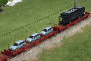
Instead of a cargoBay, the flatbed wagon has 4 slots defined in the loadIndicator, one for the bus that uses the whole cargo waggon and three for the smaller cars that are placed next to each other. The car slots have more than one possible model that can be displayed. It is randomly selected which one should be displayed.
The cargoSlots struct contains two configurations from which one is randomly selected. One configuration only uses the slot with the bus, the other configuration uses the three car slots.
CargoLanes
For static models, there is also the possibility to define cargoLanes as indicators:
loadIndicator = {
  configs = {
    indicator_1 = {
      cargoLanes = {
        nodes = {
          {
            { 0, 0, 0, },
            { 10, 0, 0, },
            4,
          },
          {
            { 10, 0, 0, },
            { 10, 0, 0, },
            4,
          },
        },
        renderDistance = 500,
      },
    },
  },
},
The nodes list contains an equal number of node definitions, each with:
- a
Vec3defining the position of the node - a
Vec3defining the outgoing/incoming tangent of the node - the width of the lane, only used from the first node.
Models of the generic cargo model formats SMALL and BIG will be used. The renderDistance can be used to set a custom maxmimum render distance for the emitted cargo models.
LabelList
In Transport Fever 2, vehicles and constructions may display some dynamic text labels. These are defined in a labelList struct in the model metadata which contains a labels list:
  ..
  labelList = {
    labels = {
      {
        childId = "RootNode",
        type = "LINE_NAME",
        transf = { 0, -1, 0, 0, 0, 0, 1, 0, 1, 0, 0, 0, -5.8043 , 0.1814, 2.808 , 1, },
        size = { 0.366, 0.210 },
        color = {247 / 255, 147 / 255, 33 /255},
        fitting = "CUT",
        alignment = "CENTER",
        nLines = 1,
        filter = "NUMBER",
        renderMode = "EMISSIVE",
      },
      ...
    },
  },
  ..
There are many different properties which can be used to define the labels:
To set the position of the label, use the transf property pointing to the coordinates where the lower left corner of the label should be. The label will be placed aligned to the X and Z axis. The coordinates are relative to the mesh that is referenced in childID by name.
The size contains a pair of two values. The first for the size in x direction, the second for the size in y direction, both relative to the transf. Negative values will result in no text visible. The y direction is used for the fontsize too. To use the label with more than one line of text, set nLines to a value larger than 1. Values below 1 are ignored.
Coloring the text is possible by using the color attribute. It receives a vector with three values, one for each color in the range between 0 and 1. The transparency of the text is set by alpha. Value 0 is invisible, value 1 is opaque, values greater than 1 might lead to artifacts. With the alphaMode, it is possible to define how the alphablending is done. Possible values are either "CUTOUT", "BLEND" or "NONE". In Front of opaque textures, this might be irrelevant, but on transparent faces like glass panes it might be more relevant. To get emissive text (like with LCD destination displays), set the renderMode to "EMISSIVE", otherwise set it to "STD".
The horizontal alignment of the text can be set in alignment with the values "LEFT", "CENTER" and "RIGHT". For the vertical alignment, set verticalAlignment either to "BOTTOM", "CENTER" or "TOP".
To adjust the behavior of text that is longer than the label, set fitting either to:
"NONE"to let it overflow."CUT"to cut excessive text."SCALE"to scale down until it fits in the horizontal size.
The type property contains one of the following keys:
"NONE"is applicable to all models and shows nothing."LINE_NAME"is applicable to vehicles and shows the name of the line that the vehicle is currently on."NEXT_STOP"is applicable to vehicles and shows the name of the next stop of the vehicle."NAME"is applicable to any model and shows the name of the entity (vehicle, construction, …)."COMPANY_NAME"is applicable to any model and shows the name of the company."STATION_NAME"is applicable to any station model and shows the station name."CUSTOM"shows some custom content based on alabelTextproperty in the construction.
The filter property is used to filter the input from the type. It can either be set to NONE to not filter, NUMBER to filter anything that is no number or CUSTOM to set advanced filters in the params struct. It contains advanced parameters to influence the text that should be displayed:
expris a regular expression that can be used to filter the input string, e.g. to only show text or some letters. If the regular expression does not match, no text is displayed. To test some regular expressions, you may use online tools like regex101.com.replacecan contain a gap text that has placeholders which are replaced by the contents or parts of the string matching the regular expression above.\\0is replaced by the part of the string that matches the complete regular expression,\\<number n>is replaced by the part of the string that matches the content of the nth ( … ) bracket pair in the regular expression.offsetcan be used together withtype = "NEXT_STOP"to display a stop further down the line.relative = falseis used together withtype = "NEXT_STOP"to start from the first station of the list (+offset). Withrelative = truethe vehicles next stop is considered instead of the first stop.
The font parameter currently only supports the vanilla fonts Lato and Noto. Other fonts than the standard ones are not allowed and lead to crashes.
It is recommended to test the labels with the model editor.
LightSourceList
Light sources can be used to illuminate surrounding models with light:
lightSourceList = {
	lights = {
		{
			lightId = "",
			meshId = "headlights_fw",
			transf = { 0.966, 0, -0.258, 0, 0, 1, 0, 0, 0.258, 0, 0.966, 0, 0, 0, 0, 1, },
			mask = 0,
			invertMask = true,
			backFaceLit = false,
			mode = "LIGHT",
			color = { 0.901960790157318115234375, 0.8577506542205810546875, 0.65082657337188720703125, },
			strength = 3,
			type = "SPOT",
			angleMax = 35,
			angleMin = 5,
			fromTime = 18,
			toTime = 7,
			visibleFrom = -1,
			visibleTo = 1600,
			fadeOutStart = 1400,
		},
	},
},
The lights can be named with an individual lightId. They are positioned with a transf that is relative to the mesh referenced in meshId. If a parent mesh is scaled , the intensity of the light source is scaled the same way. This allows switching off light sources by hiding meshes with an animation.
To restrict the light source to certain materials, the mask property can be used. It corresponds with the light receiver property bitset of the material definitions:
- 0 = Nothing
- 1 = Terrain materials
- 2 = Exterior/Standard materials (Models, Labels, …)
- 4 = Water / Ship Foam / Waves
- 8 = Particles
- 16 = (reserved)
- 32 = Interior materials
- 64 = (reserved)
If there is at least a matching bit, the materials are affected by this light source. In practice, most exterior lights have value 0 and invertMask set to true, only interior lights of vehicles have value 32 and invertMask set to false. To shine light on meshes which face away from the light source, set backFaceLit to true.
The mode defines the behavior of the light source. It is one of the three values:
LIGHTis the normal mode. The light source emits light in thecolorwith the definedstrength.ABSORBERis the inverse mode. The light source consumes light and makes it surrounding darker, depending on thestrength.DISCARDcuts out meshes within its geometric shape. It can be used to fine tune entrances of tunnels and staircases to the underground.
There are several geometric types for the light sources. They are selected by setting the type property:
SPOTis a light cone starting fromposition. It is defined by it'sradiusas well asangleMinandangleMax. The former sets the length of the cone, the later two set the width. If the two angle values are further apart from each other, the cone border is smooth, otherwise it is a sharper contour. It is recommended for vehicle headlights.POINTis a sphere around theposition. It is defined by it'sradius. It is recommended for additional exterior lights, e.g. positional lights of planes.CYLINDRICALis a cylinder withlengthandradius. The light is emitted from its middle axis outwards. It is recommended for the interior of vehicles.CHEAP_CYLINDRICALis an optimized cylinder light which only emits light sideways and not diagonal along its axis. This is recommended for larger cylinders due to performance reasons.PARALLELis a cubic shape withlength,widthandheight. The light beams are emitted unidirectional.
To use lights only during certain times or darkness, it is possible to set both a fromTime and toTime which are either values between 0 and 24 or -1. If both are set to -1, the lights switch on when it gets dark due to night time or heavy rain.
To adjust the render distance of the lights, there are visibleFrom and visibleTo, both in meters from camera. The light will be visible while its parent node is rendered and it is within the two visibility values. A smooth fade out can be set with fadeOutStart, then the light will start to get darker until it completely fades out at the visibleTo distance.
For performance reasons, the light sources should be used in reasonable quantity. For vehicles and buildings with a lot of modeled lights, it is better to place some larger atmospheric light emitters at strategic positions instead to illuminate the whole scenery. Building windows can make use of the less performance impacting light materials instead of light sources.
ParticleSystem
Particle emitters can be used to emit smoke, steam, dust or mist particles and show flames.
    particleSystem = {
      emitters = {
        {
          particleId = "",
          child = "RootNode",
          position = { 4.3632001876831, 0, 3.8589000701904, },
          ...
        },
        ...
      },
    },
The emitters have many different mostly optional properties that can be used to describe their behavior over the lifetime of the particles.
| Property | Description | Data Type | Default |
|---|---|---|---|
particleId | Identifier for reference in transformator | String | none |
child | Node of model where emitter is attached | String | required |
position | Position relative to node | Vec3(Number) | {0.0, 0.0, 0.0} |
albedoTexture | Custom texture | File Reference | |
normalMapTexture | Custom normal map | File Reference | |
frequency | Particles per second | Number* | required |
lifeTime | Max age of particle | Number* | required |
alphaOverLifeTime | Transparency depending on particle age | Curve(Number) | 0.0 → 0.0, 1.0 → 1.0 |
colorOverLifeTime | Color depending on particle age | Curve(Vec3) | 1.0 → {0.0, 0.0, 0.0} |
emissiveScale | Brightness depending on particle age | Curve(Number) | 1.0 → 1.0 |
velocity | Particle movement vector | Vec3(Number)* | {0.0, 0.0, 0.0} |
velocityOverLifeTime | Movement depending on particle age | Curve(Vec3(Number)) | 1.0 → {0.0, 0.0, 0.0} |
velocityDampingFactor | Damping of particle movement | Number | 2.5 |
sizeOverLifeTime | Particle sprite size | Curve(Number*) | 1.0 → 0.0 |
gravity | Vertical force applied on particle | Number* | 0.0 |
directionMovementFactor | Intensity of random direction | Number* | 1.0 |
noiseFactor | Intensity of noise texture overlay | Number* | 1.0 |
rotation | Static rotation of sprite | Number* | 0.0 |
rotationByDirection | Rotation relative to random direction | Number* | 180.0 |
rotationSpeed | Factor of rotation speed | Number* | 0.0 |
frame | Specific frame of texture | Integer* | 0 |
frameSpeed | Factor of frame switching speed | Number* | 0 |
frameProgressOverLifeTime | Number of cycles through all frames | Number* | 0 |
numFrames | Number of columns and rows in texture | Vec2(Integer, Integer) | {1, 1} |
animateInvisible | Computes particles out of screen | Boolean | False |
maxDistance | Rendering distance for particles | Number | 100 |
Properties marked with * can either be a static value or they can be randomized:
frequency = {
  value = 30,
},
frequency = {
  randomMinMax = {
    min = 10,
    max = 30,
  }
},
Properties with data type Curve have a list of time stamps with assigned values. The times are in the range between 0.0 and 1.0:
alphaOverLifeTime = {
  curve = {
    {
      time = 0.0,
      value = 0.0,
      easing = "Linear" -- is ignored
    },
    {
      time = 1.0,
      value = 0.5,
      easing = "Linear"
    }
  }
},
sizeOverLifeTime = {
  curve = {
    {
      time = 0.0,
      value = {
        value = 1,
      }
      easing = "Linear" -- is ignored
    },
    {
      time = 1.0,
      value = {
        randomMinMax = {
          min = 10,
          max = 30,
        }
      }
      easing = "Linear"
    }
  }
},
For easing, the following values are available: Linear, EaseOutSqrt, EaseInSine, EaseOutSine, EaseInOutSine, EaseInQuad, EaseOutQuad, EaseInOutQuad, EaseInCubic, EaseOutCubic, EaseInOutCubic, EaseInQuart, EaseOutQuart, EaseInOutQuart, EaseInQuint, EaseOutQuint, EaseInOutQuint, EaseInExpo, EaseOutExpo, EaseInOutExpo, EaseInCirc, EaseOutCirc, EaseInOutCirc, EaseInBack, EaseOutBack, EaseInOutBack, EaseInElastic, EaseOutElastic, EaseInOutElastic, EaseInBounce, EaseOutBounce, EaseInOutBounce. See easings.net for further details about the individual easing variants.
Particles can be rather performance heavy, hence it is important to find reasonable compromises for frequency and lifeTime. Both the animateInvisible and maxDistance have a large impact as well. Hence the animateInvisible flag should only be set to true for large and obvious particles that can be seen from far apart and that have a long lifeTime, e.g. the main exhaust of steam engines. Keep the maxDistance as small as possible.
Transformator Config
In comparison to the previous games, events for animation and particles in Transport Fever 3 are not hardcoded but triggered by a transformator script referenced in the transformatorConfig property of the models. This allows either relying on the default ones provided by the basegame or using custom ones to add individual functionality.
transformatorConfig = {
  transformator = {
    name = "::/vehicle/train/shared/default_train.trf",
  },
  params = {
    pantographMax = 5.9,
    pantographMin = 3.9,
  },
  skipFromLod = 2,
},
The name property references to the transformator script definition file. See Vehicle Advanced Topics for more info about the transformator details. It is possible to forward model specific data to the transformator script by listing it in params.
To reduce the performance impact, it is recommended to exclude the far distant LODs by specifying the first LOD to be skipped in skipFromLod. All further LODs are skipped to. If unset, the default is LOD 1.